|
The sectioned view of the spray gun above is a good example of
how an air atomizing spray gun works. The blue color represents
the path of the air. The red color is the finish material.
While different manufacturers may have the location or
operation of their controls a little different from one another,
the basic concept of atomization will be the same for all
manufactures, as well as, for gravity feed, siphon feed or
pressure feed guns. Air Assisted Airless guns operate a little
differently and we will discuss those separately.
As stated earlier in the book, the way a spray gun works is that
it takes the liquid from a cup or tank, and lets a stream of
this liquid flow between some controlled jets of compressed air.
As the material flows between the jets they break apart the
stream of liquid into little droplets. Other jets create a rush
of air that carries the droplets away and onto the target that
is being finished. The factors that determine how well a spray
gun does this job are :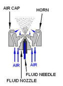
· How big in diameter
is the stream of liquid;
· How fast is it
flowing past the jets of air;
· How much air is
breaking the stream into droplets; and,
· How much air is
carrying these droplets away.
All of
these factors are directly influenced by the viscosity of the
material you are spraying.
Regardless of any of the other manufacturer features, the gun
components that controls these factors are the fluid nozzle,
fluid needle, and air cap.
The process starts with your fluid tip or nozzle. The tip is
chosen to match the viscosity of the material you are spraying.
High viscosity material requires a larger diameter fluid nozzle.
Thinner material uses a smaller diameter fluid nozzle. The
concept is to allow a certain flow rate, ounces per minute, of
material to pass thru the fluid nozzle and into the air jets.
The fluid needle seats itself in the opening of the nozzle. The
needle is attached to the trigger and it moves in and out of the
nozzle which starts and stops the flow of liquid. The fluid
control knob limits the travel of the needle, which in turn,
limits the flow of material out of the nozzle. You can adjust
the material flow from zero up to the total Oz/min capacity of
the nozzle. Fluid nozzles and needle valves should be matched
sets to insure a perfect fit which will prevent leakage at the
tip. This is especially true for pressure feed guns as the
material is presented to the nozzle at elevated pressures.
So now we have material flowing out of our nozzle at a
prescribed rate that is optimum for the viscosity of the liquid
we want to atomize. The air cap is the next link in the
atomizing chain. Air cap design will vary by gun type, as in
conventional versus HVLP.
HVLP air caps have larger air holes than those for conventional
guns. Air cap design will also vary by how the material is
presented to them, as in pressure feed versus siphon feed.
Pressure feed air caps are usually shorter and have larger air
holes in the horns which enable it to atomize the larger flow
rate per minute of the pressure feed gun. So when you are
setting your gun up, make sure that you have the correct air cap
for the type of gun that it is on. The second thing that you
want to check is that you have the proper air cap for the fluid
nozzle that you are using. Remember that your material is coming
out at a certain flow rate and you will need the correct amount
of air to atomize it. Too much air and you have excessive
overspray, too little air and you end up sanding a lot of orange
peel. An air cap will usually work for a range of fluid nozzle
sizes. Check your manufacturer’s part list or website for air
cap and nozzle combinations and details.
You will notice that the air cap has holes on the face and holes
on the ears (or horn of the cap). The center hole on the face is
where the fluid nozzle comes out. The holes on either side of
this center hole blow air into the material stream as it leaves
the gun. They atomize the stream as well as propel it toward the
target. By adjusting the air pressure coming into the gun you
control the flow of air through the air cap. This in turn
determines the atomization of the stream of material. Again,
too much air and you have excessive overspray; too little
air and atomization is not complete. The holes in the horns not
only aid in atomization, but they help form the spray pattern.
The fan control knob on the gun diverts air into the horns. With
little air coming to the horns, the spray pattern is a round
spot. As the air to the horn increases it changes the spot to a
fan shape. As you change from a spot to a fan, the pattern shape
does not change the flow rate of the material. This is important
to note especially when you reduce the size of the fan to do a
little spot touch-up. Remember to turn down the material flow or
runs will surely follow.
As you are starting to see, there is a balancing act going on.
You balance the material flow with the atomizing air pressure
and fan size. You set the major parameters with the selection of
the fluid nozzle/needle and air cap, followed by “fine tuning”
the system by adjusting your line of air pressure, then the fan
and fluid controls on the gun.
In a siphon feed gun the velocity of the air running through the
air cap also establishes the suction that siphons the material
from the cup. Siphon feed HVLP guns are a little touchy because
the air at the tip of an HVLP gun can not exceed 10 PSI. This
reduced pressure creates a slower exit velocity and less of
a vacuum in which to suck up the material out of the cup. You
may find that you have to over reduce high solids materials in
order for them to spray properly.
When you adjust the controls on the gun,
you may ask what are you adjusting them for?
The answer is to compensate for:
· The viscosity of the
material you are spraying.
· The pressure at which
the material is presented to the gun.
· The size of the part
you are spraying.
· The distance you hold
the gun from the part.
· The speed at which
you move the gun across the part as you spray.
This whole process can be thought of as a large mathematical
equation. If you change any one of the parameters, you can still
get the same answer by changing one or more of the remaining
parameters. If you have too much material coming out of the gun,
move the gun faster across the work, hold the gun farther away,
or turn the fluid control down. You can even do a little of
each. When you have this many variables, you have a lot of
control.
You can be comforted by the fact that
the viscosity of the material and the pressure that it is
delivered to the gun should hopefully not vary during a given
setup. It boils down to the fact that you are adjusting for
things that will change gun speed and distance, as well as the
size of the parts you are spraying. While we often unconsciously
compensate for the changes that mood, fatigue, and coffee intake
have on our physical control of the speed and distance of the
gun - it is a fact that the more consistent you are with
maintaining your target distance with what the gun was set for
will result in a more uniform final film thickness and less
material usage. The lower material usage results in lower VOCs
as well.
|